Pan Check Valve
Feature
No water hammering effect
There is no water hammering effect since the valve is closed by spring before water backflow takes place.
Thin, Small and Light Structure
PAN Check Valves have much shorter length and lighter than those of swing or lift check valves bacause the disc stroke is short and body has no flange.
Either Horizontal or Vertical Installation
PAN Check Valves can be horizontally or vertically installed bacause of their spring compression structure.
Free alteration of opening pressure
Alteration of opening pressure is available upon customer’s request.
Notice
Please contact us when the valve is used in high pressure and temperature.
Please contact us when the valve is used in excessively freguent open and close condition.
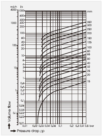
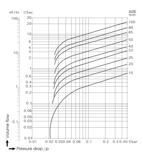
PRESSURE DROP CHART
MODEL NO. PC
1/2″(15A) ~ 4″(100A)
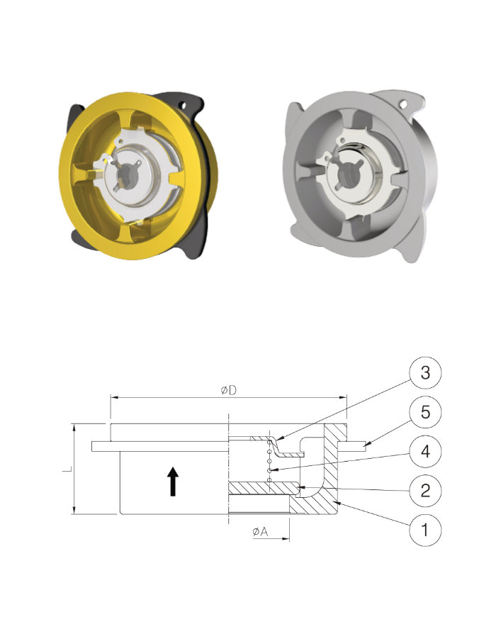
Center Rubber how to use
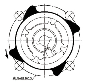
When four points of center rubbers have simultaneous contact with four bolts, it is properly centered.
Notice
Please only use for in-compressible fluid.
Specification
| Model | PC12 | PC22 | ||
| Seat | Metal | Metal | ||
| Size | ½”(15A) ~ 4″(100A) | ½”(15A) ~ 4″(100A) | ||
| Max. Pressure | 16bar | 40bar | ||
| Test. Pressure |
Shell | 24bar | 60bar | |
| Seat | 18bar | 44bar | ||
| Pipe connections | Wafer | |||
| Materials | ①Body | Forged Brass (100A:Bronze) | Stainless Steel | |
| ②Disc | Stainless Steel | |||
| Solid Teflon (-40℃ ~ +180℃, Pressure 7bar) |
||||
| ③Spring Seat | Stainless Steel | |||
| ④Spring | Stainless Steel, Inconel | |||
| ⑤Center Rubber | NBR | Stainless Steel | ||
| Pressure Drop | Please refer to Pressure drop Chart table of Page18. | |||
Dimensions
| Size mm(Inch) |
D (mm) |
L (mm) |
A (mm) |
W.T (kg) |
| 15(½) | 40 | 16 | 15 | 0.09 |
| 20(¾) | 50 | 19 | 20 | 0.12 |
| 25(1) | 60 | 22 | 25 | 0.3 |
| 32(1¼) | 73.5 | 28 | 32 | 0.5 |
| 40(1½) | 87 | 32 | 39 | 0.7 |
| 50(2) | 102 | 40 | 49 | 1.14 |
| 65(2½) | 120 | 46 | 63 | 1.83 |
| 80(3) | 132.5 | 50 | 75 | 2.45 |
| 100(4) | 158 | 60 | 93 | 3.97 |
L : Din 3202, Sheet3, Series K4
※ Above dimesions are subject to change for improvement
Opening Pressure
bar
| With spring | With spring | ||
| ↑ | → | ↓ | ↑ |
| 0.053 | 0.050 | 0.045 | 0.004 |
| 0.053 | 0.050 | 0.045 | 0.004 |
| 0.054 | 0.050 | 0.044 | 0.005 |
| 0.053 | 0.050 | 0.045 | 0.004 |
| 0.054 | 0.050 | 0.044 | 0.005 |
| 0.055 | 0.050 | 0.043 | 0.006 |
| 0.055 | 0.051 | 0.043 | 0.006 |
| 0.056 | 0.051 | 0.042 | 0.007 |
| 0.057 | 0.051 | 0.041 | 0.008 |
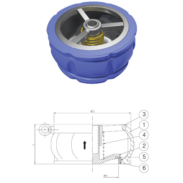
MODEL NO. PA12 / PA32
1″(25A) ~ 4″(100A)
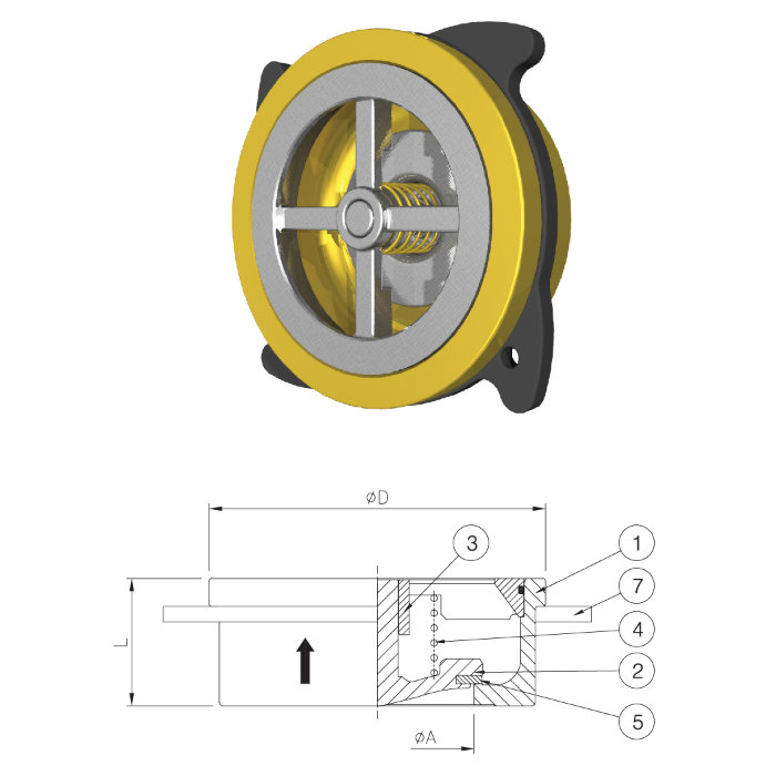
5″(125A) ~ 10″(250A)
Application
Water, Oil
Vaccum Breaker, Foot valve
Onshore, Offshore
Specification
| Model | PA12 | PA32 | ||||
| Seat | Metal | Rubber | Metal | Rubber | ||
| Size | 1″(25A) ~ 4″(100A) | 5″(125A) ~ 40″(250A) | ||||
| Max. Pressure | 16bar | 10bar | 10bar | |||
| Test. Pressure |
Shell | 24bar | 15bar | 15bar | ||
| Seat | 18bar | 11bar | 11bar | |||
| Pipe connections | Wafer | |||||
| Materials | ①Body | Forged Brass (100A:Bronze) | Ductile Cast Iron | |||
| ②Cone Disc | Stainless Steel | |||||
| ③Guide | Stainless Steel | |||||
| ④Spring | Stainless Steel, Inconel | |||||
| ⑤Disc Rubber | EPDM -10℃~+130℃ VITON -20℃~+150℃ PTEF -40℃~+180℃ |
|||||
| ⑥Valve Seat | – | Bronze Ring | ||||
| ⑦Center Rubber | NBR(25A~80A) | – | ||||
| Pressure Drop | Please refer to Pressure drop Chart table of Page18. | |||||
Dimensions
| Size mm(Inch) |
D (mm) |
L (mm) |
A (mm) |
W.T (kg) |
| 25(1) | 61 | 22 | 25 | 0.35 |
| 32(1¼) | 72.5 | 28 | 32 | 0.55 |
| 40(1½) | 87 | 32 | 39 | 0.8 |
| 50(2) | 102 | 40 | 49 | 1.1 |
| 65(2½) | 120 | 46 | 63 | 1.6 |
| 80(3) | 132.5 | 50 | 76 | 2.3 |
| 100(4) | 158 | 60 | 94 | 3.8 |
| 125(5) | 187 | 90 | 120 | 9 |
| 150(6) | 217 | 106 | 140 | 13.5 |
| 200(8) | 267 | 140 | 184 | 28.3 |
| 250(10) | 330 | 170 | 223 | 44 |
L : Din 3202, Sheet3, Series K4
※ Above dimesions are subject to change for improvement
Opening Pressure
bar
| With spring | With spring | ||
| ↑ | → | ↓ | ↑ |
| 0.055 | 0.051 | 0.043 | 0.006 |
| 0.052 | 0.048 | 0.041 | 0.005 |
| 0.055 | 0.050 | 0.042 | 0.006 |
| 0.055 | 0.050 | 0.041 | 0.007 |
| 0.056 | 0.050 | 0.040 | 0.008 |
| 0.057 | 0.050 | 0.039 | 0.009 |
| 0.058 | 0.051 | 0.035 | 0.010 |
| 0.060 | 0.051 | 0.035 | 0.012 |
| 0.060 | 0.050 | 0.032 | 0.014 |
| 0.062 | 0.049 | 0.027 | 0.018 |
| 0.064 | 0.050 | 0.025 | 0.019 |
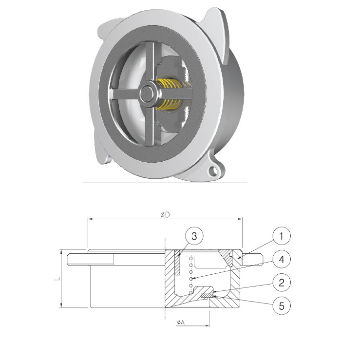
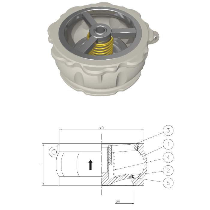
MODEL NO. PA22
1″(25A) ~ 3″(80A)
4″(100A) ~ 14″(350A)
Application
Water, Oil
Vaccum Breaker, Foot valve
Onshore, Offshore
Specification
| Seat | Metal | Rubber | |||||||||
| Size | 1″(25A)~8″(200A) | 10″(250A)~14″(350A) | 4″(100A)~14″(350A) | ||||||||
| Max. Pressure | 40bar | 20bar | 10bar | ||||||||
| Test. Pressure |
Shell | 60bar | 30bar | 15bar | |||||||
| Seat | 44bar | 22bar | 11bar | ||||||||
| Pressure and Temperature |
|
Disc Rubber | |||||||||
| Pipe connections | Wafer | ||||||||||
| Materials | ①Body | Stainless Steel | |||||||||
| ②Cone Disc | Stainless Steel | ||||||||||
| ③Guide | Stainless Steel | ||||||||||
| ④Spring | Stainless Steel, Inconel | ||||||||||
| ⑤Disc Rubber | EPDM -10℃~+130℃ VITON -20℃~+150℃ PTEF -40℃~+180℃ |
||||||||||
| Pressure Drop | Please refer to Pressure drop Chart table of Page18. | ||||||||||
Dimensions
| Size mm(Inch) |
D (mm) |
L (mm) |
A (mm) |
W.T (kg) |
| 25(1) | 61 | 22 | 25 | 0.35 |
| 32(1¼) | 72 | 28 | 32 | 0.55 |
| 40(1½) | 87 | 32 | 39 | 0.8 |
| 50(2) | 101 | 40 | 49 | 1.1 |
| 65(2½) | 120 | 46 | 63 | 1.6 |
| 80(3) | 133 | 50 | 76 | 2.3 |
| 100(4) | 158 | 60 | 94 | 3.8 |
| 125(5) | 186 | 90 | 120 | 9 |
| 150(6) | 216 | 106 | 140 | 13.5 |
| 200(8) | 267 | 140 | 184 | 28.3 |
| 250(10) | 330 | 170 | 223 | 44 |
| 300(12) | 403 | 192 | 251 | 75 |
| 350(14) | 447 | 222 | 293 | 94 |
L : Din 3202, Sheet3, Series K4
※ Above dimesions are subject to change for improvement
Opening Pressure
bar
| With spring | With spring | ||
| ↑ | → | ↓ | ↑ |
| 0.055 | 0.051 | 0.043 | 0.006 |
| 0.052 | 0.048 | 0.041 | 0.005 |
| 0.055 | 0.050 | 0.042 | 0.006 |
| 0.055 | 0.050 | 0.041 | 0.007 |
| 0.056 | 0.050 | 0.040 | 0.008 |
| 0.057 | 0.050 | 0.039 | 0.009 |
| 0.058 | 0.051 | 0.038 | 0.010 |
| 0.060 | 0.051 | 0.035 | 0.012 |
| 0.060 | 0.050 | 0.032 | 0.014 |
| 0.062 | 0.049 | 0.027 | 0.018 |
| 0.064 | 0.050 | 0.025 | 0.019 |
| 0.068 | 0.048 | 0.016 | 0.026 |
| 0.068 | 0.050 | 0.019 | 0.024 |
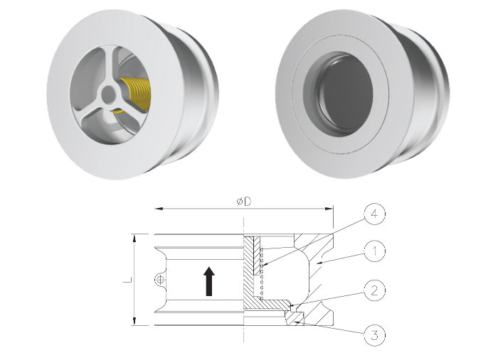
MODEL NO. ANA
1/2″(15A) ~ 4″(100A)
PRESSURE DROP CHART
Application
Water, Oil
Vaccum Breaker, Foot valve
Onshore, Offshore
Specification
| Seat | Metal | ||||
| Size | ½”(15A) ~ 4″(100A) | ||||
| Max. Pressure | Class 150 (PN20) | Class 300 (PN50) | Class 600 (PN100) | ||
| Test.Pressure | BODY | 29bar | 76bar | 147bar | |
| DISC SEAT | 21bar | 55bar | 109bar | ||
| Pressure and Temperature | ASME B16.34 Pressure and Temperature Reference |
||||
| Pipe connections | Water | ||||
| Materials | ①Body | Stainless Steel | |||
| ②Cone Disc | Stainless Steel | ||||
| ③Seat | Stainless Steel | ||||
| ④Spring | Stainless Steel, Inconel, etc. | ||||
Dimensions
| Size mm (Inch) | Class(PN) | D(mm) | L(mm) | W.t (kg) |
| 15(½) | 150(20) | 48 | 25 | 0.2 |
| 300(50) | 53 | 25 | 0.25 | |
| 600(100) | 53 | 25 | 0.3 | |
| 20(¾) | 150(20) | 57 | 31.5 | 0.37 |
| 300(50) | 65 | 31.5 | 0.46 | |
| 600(100) | 65 | 31.5 | 0.55 | |
| 25(1) | 150(21) | 65 | 35.5 | 0.47 |
| 300(51) | 70 | 35.5 | 0.54 | |
| 600(101) | 70 | 35.5 | 0.65 | |
| 32(1¼) | 150(21) | 76 | 40 | 0.7 |
| 300(51) | 80 | 40 | 0.77 | |
| 600(101) | 80 | 40 | 0.92 | |
| 40(1½) | 150(22) | 85 | 45 | 1 |
| 300(52) | 92 | 45 | 1.2 | |
| 600(102) | 92 | 45 | 1.44 | |
| 50(2) | 150(22) | 104 | 60(56) | 1.8 |
| 300(52) | 109 | 60(56) | 2 | |
| 600(102) | 109 | 60(56) | 2.4 | |
| 65(2½) | 150(23) | 123.5 | 67(63) | 2.7 |
| 300(53) | 127.5 | 67(63) | 2.9 | |
| 600(103) | 127.5 | 67(63) | 3.48 | |
| 80(3) | 150(23) | 136.5 | 73(71) | 3.7 |
| 300(53) | 146 | 73(71) | 4.3 | |
| 600(103) | 146 | 73(71) | 5.16 | |
| 100(4) | 150(24) | 174.5 | 73(80) | 6.8 |
| 300(54) | 178 | 73(80) | 7.1 | |
| 600(104) | 191 | 73(80) | 8.52 |
L(surface spacing) : The ASME B16.10 standards and ( ) inside dimensions Din 3202, Sheet 3, Series K5 standards.
※ Above dimesions are subject to change for improvement
MODEL NO. PCS
¼“(8A) ~ 2″(50A)
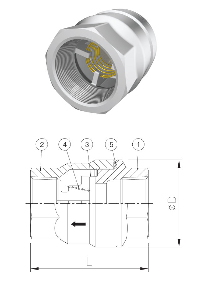
Specification
| Seat | Metal | ||
| Size | 1/2″(15A) ~ 2″(50A) | ||
| Max. Pressure | 20bar | ||
| Test. Pressure(Body) | 30bar | ||
| Pipe connections | Screwed | ||
| Materials | ①Body | Stainless Steel | |
| ②Cap | Stainless Steel | ||
| ③Disc | Stainless Steel Solid Teflon (-40℃~+180℃, Pressure 7bar) |
||
| ④Spring | Stainless Steel | ||
| ⑤O-Ring | NBR | ||
Dimensions
| Size mm(Inch) |
D (mm) |
L (mm) |
W.T (kg) |
| 15(½) | 35 | 48 | 0.18 |
| 20(¾) | 43 | 61 | 0.3 |
| 25(1) | 54 | 73 | 0.6 |
| 32(1¼) | 62 | 81 | 0.8 |
| 40(1½) | 75 | 87 | 1.2 |
| 50(2) | 90 | 100 | 1.8 |
MODEL NO. PAS
1″(25A) ~ 2″(50A)
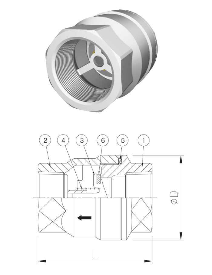
Specification
| Seat | Metal Touch | Rubber Touch | ||
| Size | 1″(25A) ~ 2″(50A) | |||
| Max. Pressure | 20bar | 10bar | ||
| Test. Pressure(Body) | 30bar | 15bar | ||
| Pipe connections | Screwed | |||
| Materials | ①Body | Stainless Steel | ||
| ②Cap | Stainless Steel | |||
| ③Disc | Stainless Steel | |||
| ④Spring | Stainless Steel | |||
| ⑤O-Ring | NBR | |||
| ⑥Disc Rubber | EPDM -10℃~+130℃ VITON -20℃~+150℃ |
|||
Dimensions
| Size mm(Inch) |
D (mm) |
L (mm) |
W.T (kg) |
| 25(1) | 54 | 73 | 0.6 |
| 32(1¼) | 62 | 81 | 0.8 |
| 40(1½) | 75 | 87 | 1.2 |
| 50(2) | 90 | 100 | 1.8 |
MODEL NO. CV
½“(15A) ~ 2″(50A)
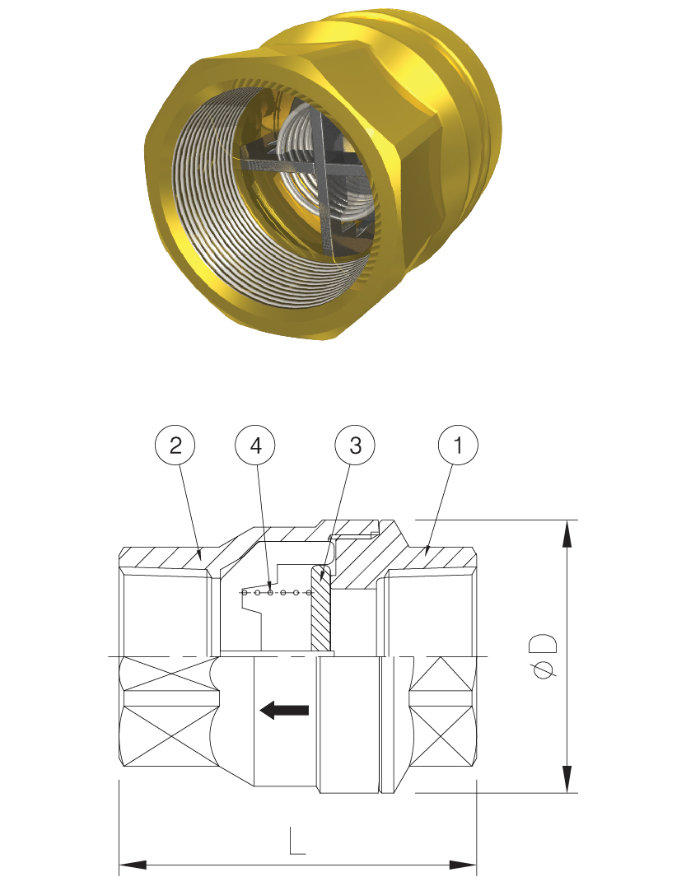
Specification
| Seat | Metal | ||
| Size | ½”(15A) ~ 2″(50A) | ||
| Max. Pressure | 10bar | ||
| Test. Pressure(Body) | 15bar | ||
| Pipe connections | Screwed | ||
| Materials | ①Body | Forged Brass | |
| ②Cap | Forged Brass | ||
| ③Disc | Stainless Steel Solid Teflon (-40℃~+180℃, Pressure 7bar) |
||
| ④Spring | Stainless Steel | ||
Dimensions
| Size mm(Inch) |
D (mm) |
L (mm) |
W.T (kg) |
| 15(½) | 33 | 48 | 0.15 |
| 20(¾) | 41 | 58 | 0.26 |
| 25(1) | 50.4 | 66 | 0.49 |
| 32(1¼) | 58 | 74.5 | 0.65 |
| 40(1½) | 71 | 84.5 | 1.2 |
| 50(2) | 88 | 95.5 | 1.2 |
Opening Pressure
0.05 bar
MODEL NO. UCV
½“(15A) ~ 2″(50A)
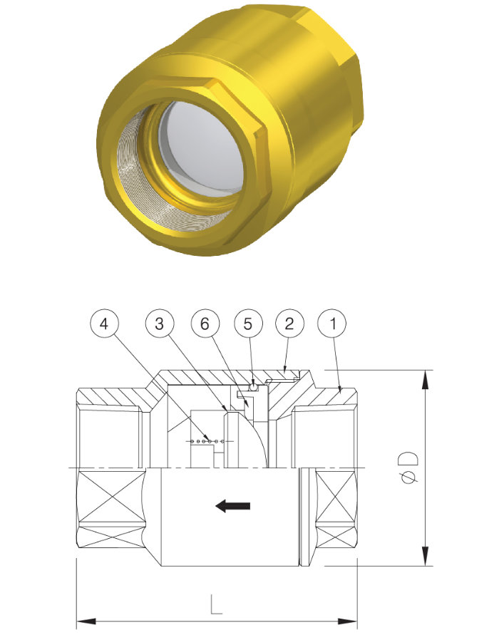
Features
Suitable for low working pressure
Less noise
Specification
| Seat | Rubber Touch | ||
| Size | ½”(15A) ~ 2″(50A) | ||
| Max. Pressure | 10bar | ||
| Test. Pressure(Body) | 15bar | ||
| Pipe connections | Screwed | ||
| Materials | ①Body | Forged Brass | |
| ②Cap | Forged Brass | ||
| ③Valve Unit | POM | ||
| ④Spring | Stainless Steel | ||
| ⑤O-Ring | NBR | ||
| ⑥Disc Rubber | EPDM | ||
| Max.Temp | Max, 80℃ | ||
Dimensions
| Size mm(Inch) |
D (mm) |
L (mm) |
W.T (kg) |
| 15(½) | 31.6 | 51 | 0.11 |
| 20(¾) | 40 | 58 | 0.25 |
| 25(1) | 51.7 | 69 | 0.4 |
| 32(1¼) | 60 | 80 | 0.6 |
| 40(1½) | 75 | 93 | 1.1 |
| 50(2) | 94 | 102 | 1.5 |
Opening Pressure
0.05 bar
MODEL NO. BU
¼”(8A) ~ ¾“(20A)
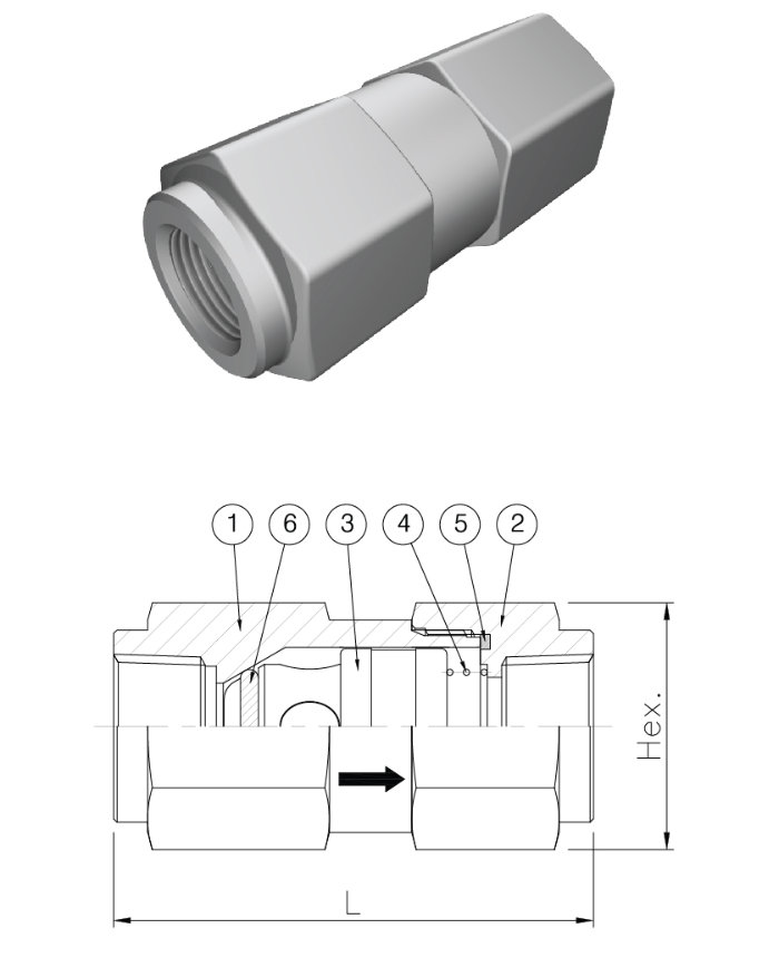
Specification
| Materials | Stainless Steel |
| Max. Pressure | Rubber : 20bar |
| Test. Pressure | 30bar |
| Part name | ①Body ②Cap ③Poppet ④Spring ⑤O-Ring ⑥Seat O-Ring |
Dimensions
| Size mm(Inch) |
HEX (mm) |
L (mm) |
W.T (kg) |
| 8(¼) | 22 | 57 | 0.13 |
| 10(⅜) | 22 | 57 | 0.13 |
| 15(½) | 32 | 70 | 0.31 |
| 20(¾) | 38 | 82 | 0.48 |
Above dimesions are subject to change for improvement
Opening Pressure
0.1 bar (Horizontal pipe standards)
MODEL NO. KAI
¼”(8A) ~ 1″(25A)
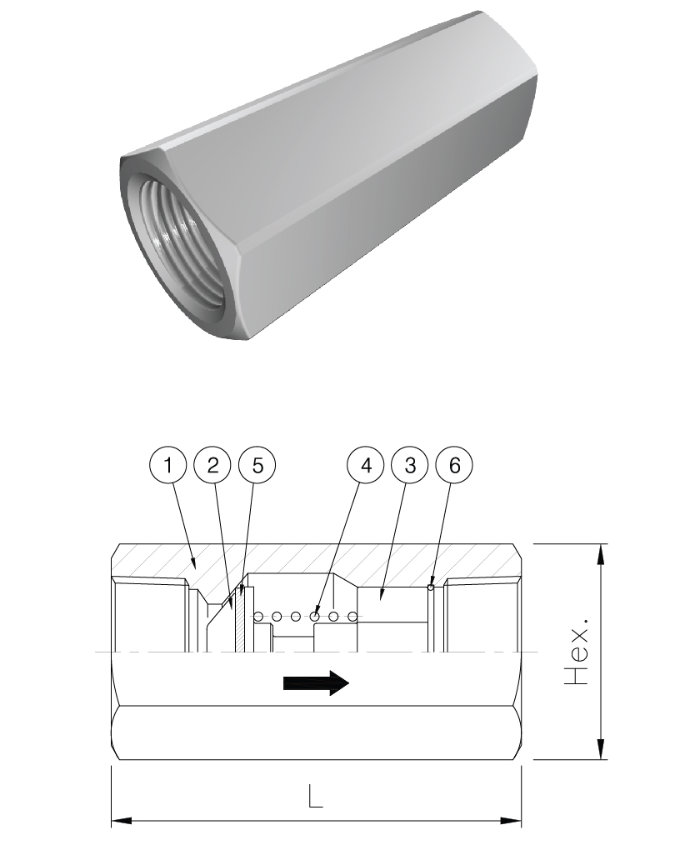
Specification
| Materials | Stainless Steel / C3604 |
| Max. Pressure | 20bar |
| Test. Pressure | 30bar |
| Part name | ①Body ②Disc ③Guide ④Spring ⑤Seat O-Ring ⑥Stop Ring |
Dimensions
| Size mm(Inch) |
HEX (mm) |
L (mm) |
W.T (kg) |
| 8(¼) | 16 | 41.6 | 0.06 |
| 10(⅜) | 22 | 52 | 0.15 |
| 15(½) | 27 | 62 | 0.25 |
| 20(¾) | 36 | 73 | 0.55 |
| 25(1) | 41 | 90 | 0.84 |
Above dimesions are subject to change for improvement
Opening Pressure
0.1 bar (Horizontal pipe standards)
